What I was trying to say, if VS or HS change as the PCLK is rising, then it
may not register, but the next PCLK clock should register the VS or HS
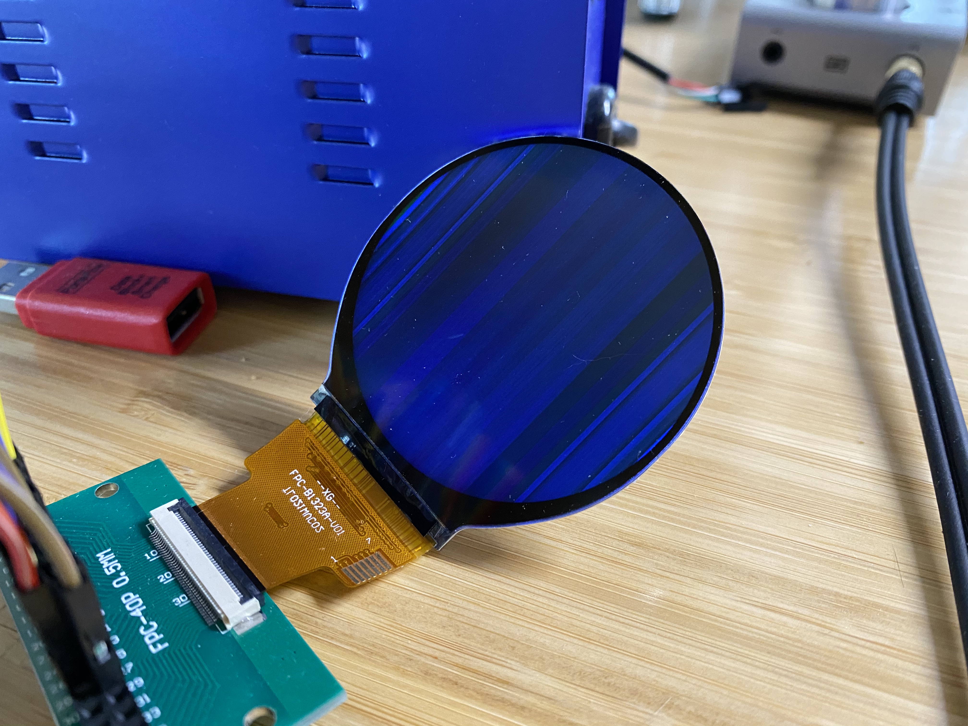
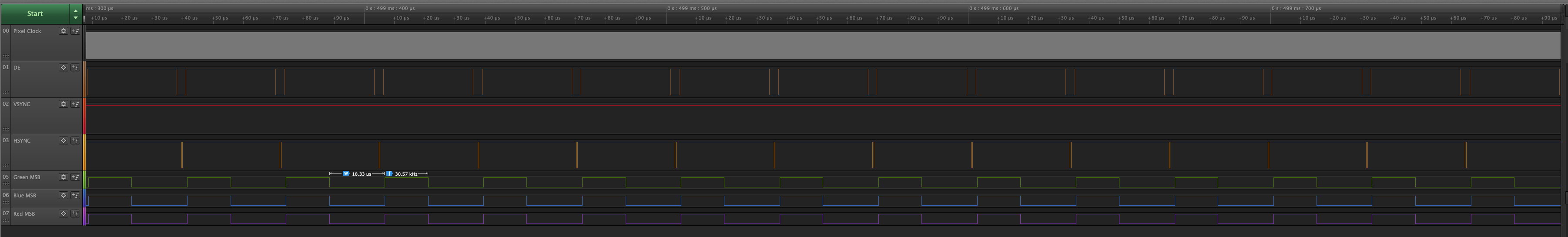
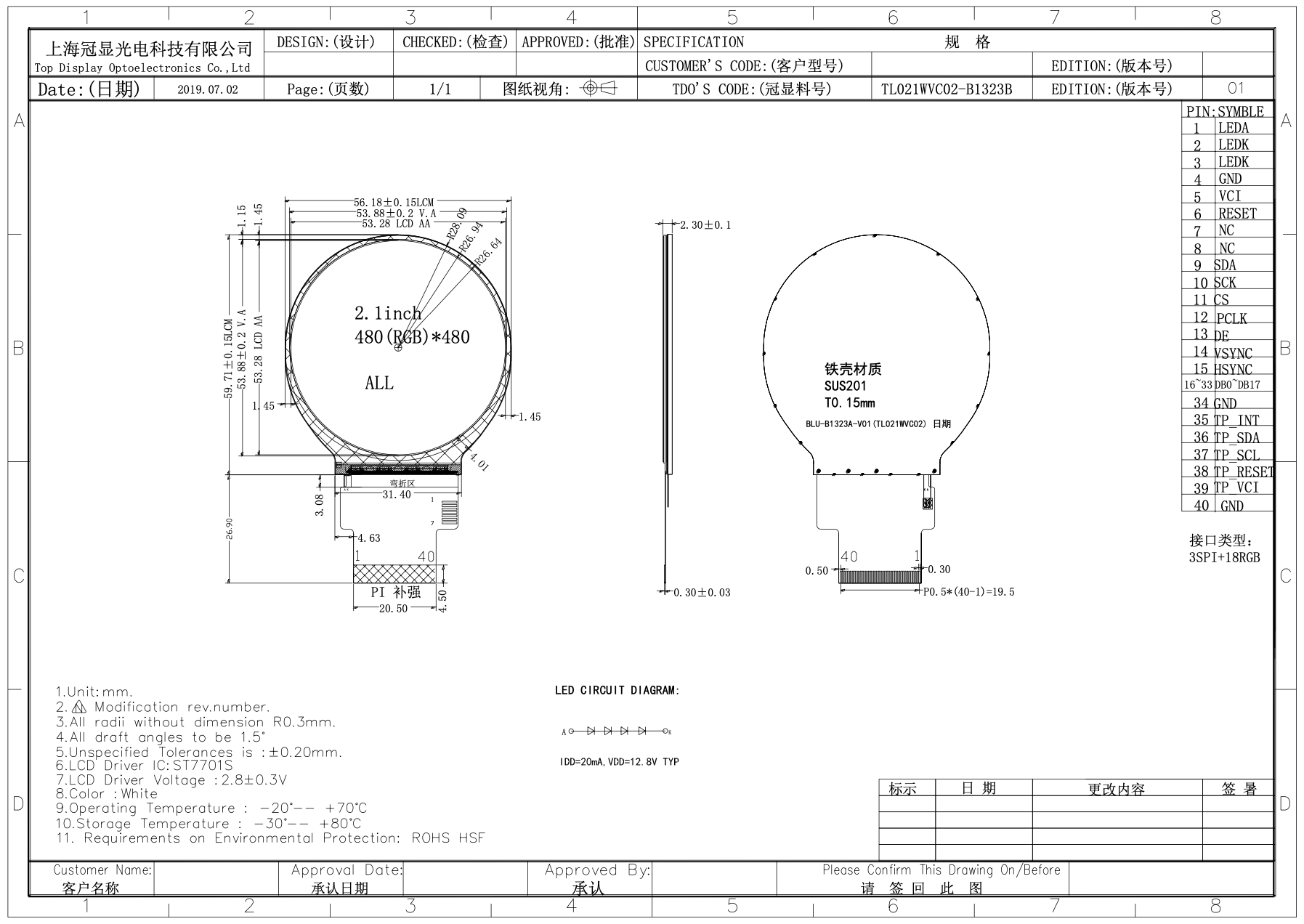
On Sunday, 3 May 2020 11:44:31 UTC+1, Robert Forsyth wrote:
>
> The Densitron DMT040QBHTNT0-1A data sheet has much useful info.
> DE Mode:
> VS and HS are inverted (active low)
> DE and DOTCLK (active-high)
>
> HV Mode:
> VS and HS are active-low
> PCLK active-high
> DE always 1
>
> SPI:
> SPI has 4 clock modes
> SCK/SCL is active-high (normally low on fall of active-low CS)
> clocks data in on first rising edge
> clocks data out on first falling edge after first rising edge
>
>
>
> On Monday, 30 March 2020 22:34:30 UTC+1, Corey Vixie wrote:
>>
>> Hi folks. For some months now, I've been trying to get a small LCD based
>> on the Sitronix ST7701S working with the BeagleBone Black. Because the
>> Linux kernel only includes a MIPI DSI driver for the ST7701 (which is
>> similar but not identical), I wrote my own SPI driver in Rust. It's
>> open-source, available here:
>> https://github.com/ironblock/ST7701S-SPI-Driver
>>
>> My problem is that no matter what kind of image I try and display, the
>> output is garbled. I see no distinct pixel color values across an entire
>> column (or maybe they're lines? I'm not sure which way is up).
>>
>> I've connected it using the 16-bit pinmux, since that seemed "safest". My
>> SPI commands work, and doing things like "turn all pixels on", "turn all
>> pixels off", "invert colors", etc. all work as expected, but the image is
>> never clear.
>>
>> I put 33R resistors on the data lines in case there was some kind of
>> reflection or interference that was causing the problem.
>>
>> I'm currently powering the LCD driver from P9.3 (VDD 3.3v). The Sitronix
>> data sheet indicates that this is allowed, but the LCD vendor's data sheet
>> says 2.8v±0.3v. So, maybe I'm over-volting it?
>>
>> The vendor tells me that the display should be set to 480x480@60Hz. Using
>> other resolutions like standard VGA shifts the garbled image as though the
>> porches were being respected.
>>
>>
>> A public link to the data sheet is here. This is the same as the one I've
>> been provided by my vendor:
>> https://focuslcds.com/content/ST7701S_SPEC_%20V1.2.pdf
>>
>> The GitHub contains the dts and uEnv.txt files (or I can copy them here,
>> if linking out is disallowed in this group).
>>
>> I've copied most of my Github issue below:
>> https://github.com/ironblock/ST7701S-SPI-Driver/issues/1
>>
>> I appreciate any insight anyone may have. I'm honestly not sure what else
>> to try. As a disclaimer, I'm new to both Rust and hardware development, so
>> there's a lot I don't know.
>>
>> I'm happy to answer any questions or provide any additional information.
>>
>> Thanks!
>> --Corey
>>
>>
>> -------
>>
>> Using fim to render a pure white png produces this:
>> [image: IMG_6400]
>> <https://user-images.githubusercontent.com/5800173/77863664-c4643e80-71d8-11ea-85a0-891d10fce45c.jpeg>
>>
>> The OS is Debian Stretch 9.5 IoT from the Beaglebone website.
>>
>> The display is connected as per the normal
>>
>> The chosen resolution is 480x480@60Hz. I've also tried the CVT RB and CVT
>> RBv2 variants of standard VGA (640x480@60Hz, which should be supported by
>> the ST7701S), and the results are the same, just shifted on the display.
>> All tested configurations are visible in the device tree overlay.
>>
>> Using fim to display other test images produces similar results. My pure
>> black png is dark, a color test pattern produces some green effects, etc.
>>
>> Testing the signal lines with a logic analyzer shows the expected values
>> when sampling the MSB for each color. An excellent example is using a test
>> image like this:
>> [image: image004]
>> <https://user-images.githubusercontent.com/5800173/77863973-03938f00-71db-11ea-90b7-af0f03dec3af.png>
>>
>> When zoomed to the level of a single frame, everything looks correct,
>> like the datasheet. DE, VSYNC, and HSYNC polarity look good and correct.
>> The VSYNC refresh rate tested at 59.97hz, which should be appropriate for
>> the display.
>> [image: image005]
>> <https://user-images.githubusercontent.com/5800173/77864041-481f2a80-71db-11ea-87a2-acf6604e2275.png>
>>
>> When I zoom in to look at the timings for each line, everything also
>> looks correct, and you can see the white and black pattern for each line in
>> the MSB values. My logic analyzer can only sample as fast as 24MS/s, which
>> does not accurately capture the pixel clock (which is was set to 16.15MHz
>> for this test).
>> [image: image006]
>> <https://user-images.githubusercontent.com/5800173/77864052-58370a00-71db-11ea-8310-34c94181db9a.png>
>>
>> Relevant files:
>>
>>    - /boot/uEnv.txt
>>
>> <https://github.com/ironblock/ST7701S-SPI-Driver/blob/master/platforms/beaglebone/uEnv.txt>
>>    - Device tree overlay
>>
>> <https://github.com/ironblock/ST7701S-SPI-Driver/blob/master/platforms/beaglebone/VE-2IN-BBB.dts>
>>
>>
>> Here is the exact hardware setup I'm using:
>>
>> [image: IMG_6401]
>> <https://user-images.githubusercontent.com/5800173/77944579-0d1d0580-7274-11ea-9e9e-6c2901d75876.jpeg>
>>
>> [image: Screen Shot 2020-03-30 at 10 46 23 AM]
>> <https://user-images.githubusercontent.com/5800173/77944609-1908c780-7274-11ea-8aac-c3eb7855c986.png>
>> FunctionNamePinResistorPinName
>> LED ANODE +12.8v DC PSU + -- 1 LED A
>> LED CATHODE GND DC PSU - -- 2 LED K
>> LED CATHODE GND DC PSU - -- 3 LED K
>> Ground DGND P9.1 -- 4 GND
>> Power supply VDD 3.3V P9.3 -- 5 VCI
>> Reset Signal GPIO_60 P9.12 -- 6 RESET
>> Not Connected -- -- -- 7 NC
>> Not Connected -- -- -- 8 NC
>> SPI Data signal SPIO_D1 P9.18 -- 9 SDA
>> SPI Clock signal SPIO_SLCK P9.22 -- 10 SCK
>> SPI Chip select signal SPIO_CSO P9.17 -- 11 CS
>> RGB dot clock signal LCD_PCLK P8.28 33Ω 12 PCLK
>> RGB data enable signal LCD_AC_BIAS P8.30 33Ω 13 DE
>> RGB frame synchronizing signal LCD_VSYNC P8.27 33Ω 14 VSYNC
>> RGB line synchronizing signal LCD_HSYNC P8.29 33Ω 15 HSYNC
>> 📘B[0] DGND P8.1 33Ω 16 DB0
>> 📘B[1] LCD_DATA0 P8.45 33Ω 17 DB1
>> 📘B[2] LCD_DATA1 P8.46 33Ω 18 DB2
>> 📘B[3] LCD_DATA2 P8.43 33Ω 19 DB3
>> 📘B[4] LCD_DATA3 P8.44 33Ω 20 DB4
>> 📘B[5] LCD_DATA4 P8.41 33Ω 21 DB5
>> 📗G[0] LCD_DATA5 P8.42 33Ω 22 DB
>> 📗G[1] LCD_DATA6 P8.39 33Ω 23 DB
>> 📗G[2] LCD_DATA7 P8.40 33Ω 24 DB
>> 📗G[3] LCD_DATA8 P8.37 33Ω 25 DB
>> 📗G[4] LCD_DATA9 P8.38 33Ω 26 DB
>> 📗G[5] LCD_DATA10 P8.36 33Ω 27 DB
>> 📕R[0] DGND P8.2 33Ω 28 DB
>> 📕R[1] LCD_DATA11 P8.34 33Ω 29 DB
>> 📕R[2] LCD_DATA12 P8.35 33Ω 30 DB
>> 📕R[3] LCD_DATA13 P8.33 33Ω 31 DB
>> 📕R[4] LCD_DATA14 P8.31 33Ω 32 DB
>> 📕R[5] LCD_DATA15 P8.33 33Ω 33 DB
>>
>

--
For more options, visit http://beagleboard.org/discuss
---
You received this message because you are subscribed to the Google Groups
"BeagleBoard" group.
To unsubscribe from this group and stop receiving emails from it, send an email
to [email protected].
To view this discussion on the web visit
https://groups.google.com/d/msgid/beagleboard/d6206c19-9d3f-4255-a13f-cd647221d896%40googlegroups.com.